You can find GigE Vision scan examples for mE4VQ4-GE platforms in the following sections. In ' GigE Vision Area Scan Cameras ' or 'GigE Vision Line Scan Cameras' examples for area scan cameras or line scan cameras are described.
The designs for acquisition of GigE Vision cameras is very simple as can be seen in the following figures. Note that the microEnable IV VQ4-GE/-GPoE allows the connection of up to four cameras with gigabit ethernet interface. Thus, user can use all four cameras at the same time in either four different processes individually or by combining their images and use a common processing. Check 'Multiple Processes' for more information on multiple processes and ' Synchronizing Cameras ' for more information on how to combine the images of multiple cameras.
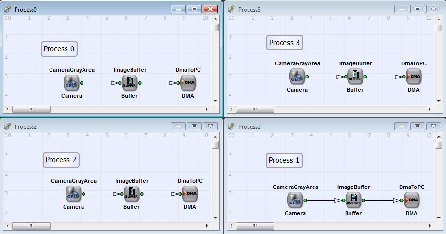
The example "DualAreaGray8.va" is a two process acquisition design for two grayscale GigE cameras with 8 bit pixel depth. The designs "QuadAreaGray8.va" and "QuadAreaGray12.va" are two 4 process designs for 4 GigE area scan cameras with 8 bit and 12 bit grayscale values. You can find the examples under \examples\Acquisition\BasicAcquisition\mE4VQ4-GE\Area. In Fig. 233 you can se the basic design structure of the 4 processes design "QuadAreaGray8.va".
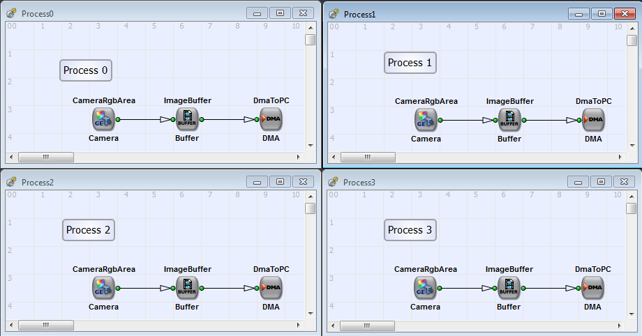
The examples "DualAreaRGB24.va" and "DualAreaRGB36.va" are dual process designs for RGB image acquisition for 24 bit (8 bit per color component) and 36 bit (12 bit per color component) pixel depth. The design "QuadAreaRGB24.va" is a quad process design and equivalent to the example in ' GigE Vision Grayscale Area Scan Cameras '. You can see its basic design structure in Fig. 234. Please find the examples under \examples\Acquisition\BasicAcquisition\mE4VQ4-GE\Area.
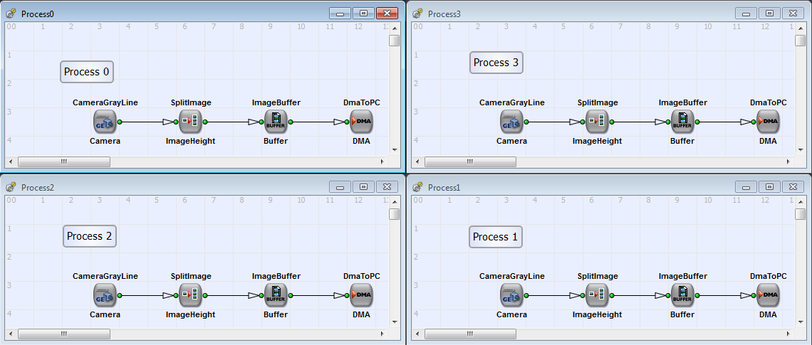
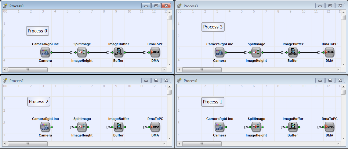
The acquisition for line scan cameras always requires the cut of the camera lines into images of a specific height. In detail, line scan cameras transfer line by line to the frame grabber. They will not include information on the end or start of a new image. The transfer of data from the frame grabber to the PC is required to be send in packages i.e. frames. Therefore, the lines from line scan cameras have to be assembled into an image of a specific height. The GigE Vision examples use the SplitImage operator (See 'SplitImage') to set a parameter defined image height to all acquired images. Another possibility is the usage of operator SignalGate (See 'SignalGate'). For more information on the data transfer of line scan cameras 'Image Protocols, Image Dimensions and Data Structure' The following designs show simple Camera Link line scan VisualApplets implementations for basic acquisition. The following designs show the basic acquisition for GigE Vision line scan cameras.
This example is a four processes design for a grayscale camera with 8 bit. You can find it under \examples\Acquisition\BasicAcquisition\mE4VQ4-GE\QuadLineGray8.va.


 Prev
Prev

